The idea: a capacitor fills through a resistor
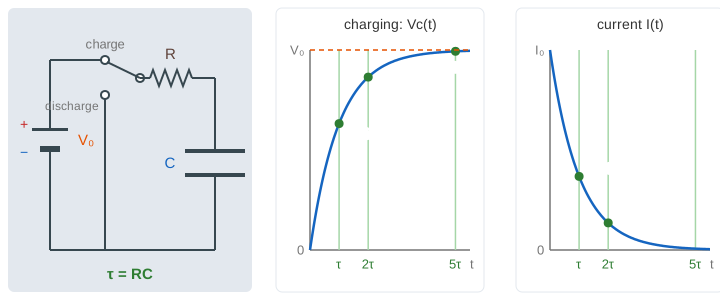
A capacitor C is two metal plates with a gap between them. Push charge onto it and one plate gets +Q, the other −Q, and a voltage Vc = Q/C appears across it. A resistor R limits the current, I = V/R. Put a battery V₀, a switch, R and C in one loop and the capacitor does not fill at once: it fills fast at first, then slower and slower. The voltage climbs along an exponential curve and the current dies away along another one.
Why it slows down
While charging, the battery's V₀ is shared between R and C: V₀ = I·R + Vc. So the current is I = (V₀ − Vc)/R. At the start C is empty, all of V₀ is across R and the current is at its biggest, I₀ = V₀/R. Every bit of charge that arrives raises Vc and leaves less push for the next bit. The current falls in proportion to the gap that is left, and that is exactly what an exponential does:
Vc(t) = V₀ · (1 − e^(−t/RC))        charging
I(t)  = (V₀/R) · e^(−t/RC)
Q(t)  = C · Vc(t)
On the page the yellow dots on the wires move by the charge that went through: they race at first and crawl at the end. The + and − signs on the plates count Q, one per 0.25 mC. The dots show the conventional current (+ charge); in a metal wire the electrons actually move the other way. (Demo 1)
The time constant τ = RC
The product τ = RC is a time: 10 kΩ × 100 μF = 1 s. After each τ only e⁻¹ ≈ 37% of the gap is left, so each τ closes 63% of what remains:
| t | charging: Vc / V₀ | discharging: Vc / V₀ | current: I / I₀ |
|---|---|---|---|
| 1τ | 63% | 37% | 37% |
| 2τ | 86% | 14% | 14% |
| 3τ | 95% | 5% | 5% |
| 4τ | 98% | 2% | 2% |
| 5τ | 99.3% | 0.7% | 0.7% |
In theory the capacitor is never quite full; engineers call it full after 5τ. The green lines in both graphs sit at τ, 2τ and 5τ, and the dots on the blue curve appear as the movie passes them.
Discharging and the half-life
Flip the switch to "discharge": the battery leaves the loop and C pushes its charge back through R. Now the whole Vc is across R, the current is −Vc/R (the other way round the loop), and
Vc(t) = V₀ · e^(−t/RC) I(t) = −(V₀/R) · e^(−t/RC)It is the charging curve turned upside down (Demo 2). Like any exponential decay it has a half-life: Vc halves every t½ = RC·ln 2 ≈ 0.69·RC, so after 2·t½ a quarter is left, after 3·t½ an eighth. With R = 20 kΩ and C = 100 μF, τ = 2 s and t½ ≈ 1.39 s (Demo 6). The same t½ is also where the charging curve is half way to V₀.
R and C: slower, more current, more charge
| change | τ = RC | start current V₀/R | full charge C·V₀ | on the page |
|---|---|---|---|---|
| R 10 → 20 kΩ | 1 → 2 s | 1 → 0.5 mA | 1 mC (same) | Demo 3 |
| C 100 → 200 μF | 1 → 2 s | 1 mA (same) | 1 → 2 mC | Demo 4 |
| R 5 kΩ, C 200 μF | 1 s (same) | 1 → 2 mA | 1 → 2 mC | Demo 5 |
| V₀ 5 → 10 V | 1 s (same) | 0.5 → 1 mA | 0.5 → 1 mC | Demo 7 |
Only the product RC sets the shape of the Vc curve. Halve R and double C and the voltage curve is the same grey line again, but twice the current flows, because twice the charge has to move in the same time (Demo 5). V₀ only scales everything up; it never changes τ.
Energy: half is always lost in R
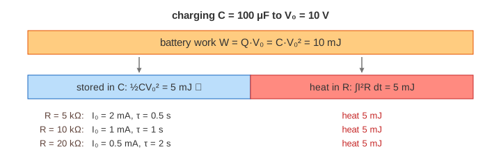
A full capacitor stores U = ½CV₀². To get there the battery pushed the charge Q = CV₀ through its whole voltage V₀, so it did W = Q·V₀ = CV₀² of work, twice as much. The other half became heat in the resistor. The surprise: this does not depend on R. A small R gives a big current for a short time, a big R a small current for a long time; the heat ∫I²R dt comes out as ½CV₀² either way. Doubling V₀ makes the stored energy four times bigger (Demo 7: 1.23 mJ → 4.93 mJ). When the capacitor discharges, the stored half turns into heat in R too.
See also
The same e^(−t/τ) decay shapes the envelope in Damped Oscillation (add a coil to the RC loop and you get an RLC circuit that rings like a damped spring), and Exponentials and Logarithms shows why ln 2 turns a time constant into a half-life. For the other kind of circuit, built from logic gates, see Arithmetic Circuits.
What the page leaves out
The battery's own internal resistance and the resistance of the wires (here they are 0), sparks and bounce in a real switch, the inductance of the loop (that gives RLC circuits and ringing), alternating voltages and RC filters, charge slowly leaking through a real capacitor, and capacitors whose C changes with voltage or temperature. The page keeps V₀ at 5–12 V, R at 5–20 kΩ and C at 50–200 μF, so τ runs from 0.25 s to 4 s, and the graphs stop at 10 s.