The idea: three parts, two kinds of memory
Almost every analog circuit is built from three passive parts. A resistor turns electrical energy into heat. A capacitor stores energy in an electric field between two plates. An inductor (a coil) stores energy in a magnetic field around its wire. The two that store energy also remember something, and that memory is why circuits take time to respond.
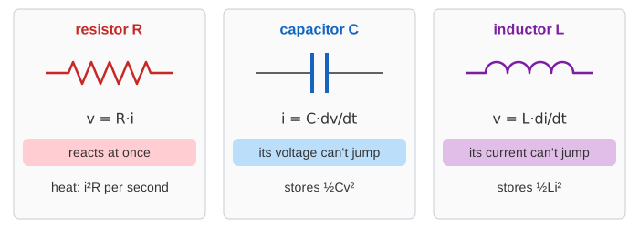
| part | rule | what can't jump | energy |
|---|---|---|---|
| resistor R (Ω) | v = R·i | nothing: it reacts at once | heat, i²R per second |
| capacitor C (F) | i = C·dv/dt | its voltage v_C | ½Cv² stored |
| inductor L (H) | v = L·di/dt | its current i_L | ½Li² stored |
A jump in v_C would need an infinite current, and a jump in i_L an infinite voltage. So at the moment a switch flips, v_C and i_L keep their values, and the resistor takes whatever change is left. On the canvas, every flip of the switch says what stays and what jumps.
Kirchhoff's laws hold at every instant
Two rules tie the parts together. Going round a loop, the voltages add up to the source (Kirchhoff's voltage law, KVL): v_R + v_L + v_C = V_s. At a junction, the currents in add up to the currents out (Kirchhoff's current law, KCL): in the parallel circuit, i_R + i_L + i_C = I_s. The bars at the top right show the law at every tick, even while v_L goes negative and v_C overshoots the source.
RC and RL: one time constant
A circuit with one storing part has one time constant τ. For RC it is τ = RC, for RL it is τ = L/R. Every quantity moves from where it was to where it is going along the same curve, e^(−t/τ): after one τ, 63.2% of the change is done.
| time after the switch | τ | 2τ | 3τ | 4τ | 5τ |
|---|---|---|---|---|---|
| share of the change done | 63.2% | 86.5% | 95.0% | 98.2% | 99.3% |
With R = 100 Ω and C = 10 µF, τ = 1 ms: v_C reaches 6.32 V after 1 ms and 9.93 V after 5 ms, while the current starts at V/R = 100 mA and dies away (Demo: RC charging, 63% at τ). Switch to B and the capacitor drains through R along the same kind of curve, with the current flowing the other way (Demo: RC charge, then discharge).
RL is the mirror image. The coil's current can't jump, so at the switch all 10 V land on the coil and the current creeps up to V/R = 100 mA with τ = L/R = 100 mH / 100 Ω = 1 ms (Demo: RL, the coil fights the change).
Breaking a coil's circuit is the dangerous part. If the current has nowhere to go, di/dt is huge, so v_L = L·di/dt is too: the inductive kick that sparks across relay contacts. Path B on the canvas gives the current a way round, which is what a flyback diode across a relay coil does (Demo: RL switched off).
Series RLC: it can ring
With both L and C, energy can swing between them. The capacitor charges, the coil keeps the current going past the point where it should stop, the capacitor overshoots, and the current turns back. R takes a bit of the energy on every swing. Two numbers decide what happens:
- the decay rate α = R/2L (parallel: α = 1/(2RC)), how fast R drains the energy;
- the natural frequency ω₀ = 1/√(LC), how fast energy swings between L and C (f₀ = ω₀/2π).
Their ratio is the damping ratio ζ = α/ω₀.
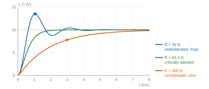
| case | condition | R (L = 10 mH, C = 10 µF) | what v_C does |
|---|---|---|---|
| underdamped | α < ω₀ (ζ < 1) | 20 Ω | overshoots to 13.51 V at 1.05 ms, rings at ω_d = √(ω₀² − α²) = 3000 rad/s (477 Hz) |
| critically damped | α = ω₀, R = 2√(L/C) | 63.2 Ω | the fastest rise with no overshoot |
| overdamped | α > ω₀ (ζ > 1) | 200 Ω | no overshoot, but a slow tail: 7.80 V after 3 ms |
The overshoot from rest is e^(−απ/ω_d): with α = 1000 /s and ω_d = 3000 rad/s that is e^(−π/3) = 35.1%, so v_C peaks at 13.51 V while the source is only 10 V. (Demo: series RLC rings, Demo: critical damping, Demo: overdamped, slow, and Demo: three R on one scope, which keeps the earlier runs in grey.) The same equation drives a mass on a spring with friction, see Damped Oscillation and Spring Oscillator: L plays the mass, 1/C the spring and R the friction.
Energy sloshing between L and C
The energy bars show where the source's energy goes. In the ringing circuit, the store moves from C (½Cv², biggest when v_C peaks) to L (½Li², biggest when the current peaks), and R takes a slice every swing. At every tick: energy from the source = ½Cv² + ½Li² + heat in R. Charging a capacitor through a resistor from a fixed source always loses exactly half the energy to heat, whatever R is: the capacitor ends with ½CV² = 0.5 mJ and the source gave CV² = 1 mJ.
Parallel RLC: the same story, turned around
Put R, L and C side by side and feed them from a current source. Now the voltage v is the same on all three and the currents add up (KCL instead of KVL). Everything turns into its dual: α = 1/(2RC), so a bigger R means less damping, and the quality factor is Q = R·√(C/L) instead of (1/R)·√(L/C). With R = 1 kΩ, L = 10 mH and C = 10 µF, Q = 31.6 and the voltage rings at 503 Hz for many cycles (τ = 2RC = 20 ms) while the coil slowly takes over the whole 0.1 A (Demo: parallel RLC rings for long).
| series RLC | parallel RLC | |
|---|---|---|
| shared by all parts | the current i | the voltage v |
| law that adds up | voltages (KVL) | currents (KCL) |
| decay rate α | R/2L | 1/(2RC) |
| critical R | 2√(L/C) = 63.2 Ω | ½√(L/C) = 15.8 Ω |
| Q | (1/R)·√(L/C) | R·√(C/L) |
| at resonance, |Z| is | smallest (= R) | biggest (= R) |
AC: impedance, phasors and resonance
Drive the circuit with a sine of frequency f and wait for the start-up to die out. Every voltage and current is then a sine of the same f, and each part has a reactance: X_L = 2πfL grows with f, X_C = 1/(2πfC) shrinks with f. The coil's voltage runs 90° ahead of its current and the capacitor's 90° behind, so on the phasor diagram V_L points up, V_C points down and V_R lies along the current. The impedance is Z = R + j(X_L − X_C), with size |Z| = √(R² + (X_L − X_C)²) (see Complex Numbers for the j).
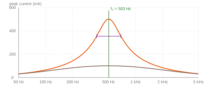
At f₀ = 1/(2π√(LC)) the two reactances are equal and cancel: |Z| = R, the current is in phase with the source and as big as it gets, 10 V / 20 Ω = 0.5 A. Below f₀ the capacitor wins (the current leads), above it the coil wins (the current lags). At resonance V_L and V_C are each Q times the source, 15.8 V from a 10 V source, but they point opposite ways and cancel. The peak's width between the two half-power points (where the current is 1/√2 of the peak) is the bandwidth f₀/Q: 318 Hz for Q = 1.58 (Demo: AC sweep through resonance, which then sets R = 100 Ω and flattens the peak). A mass on a spring pushed by a sine force has the same resonance peak: see Driven Oscillator.
A parallel tank does the opposite. At f₀, I_L and I_C cancel, so the tank draws almost nothing and its impedance peaks at R: 10 mA into 1 kΩ gives 10 V, while 316 mA swings back and forth between L and C (Demo: parallel tank at resonance). With one part only, the curve has no peak: RC passes low frequencies to the capacitor and RL passes high ones to the coil, with a corner at f_c = 1/(2πτ) (Demo: RC as a low-pass filter).
Where you meet them
- RC: switch debouncing, reset delays, the timing of a 555 timer, low-pass and high-pass filters, the delay of a wire charging a gate's capacitance.
- RL: relay and motor coils (and their flyback diodes), current ramps in switching power supplies.
- Series RLC: band-pass filters, ringing on fast digital edges (a trace's inductance and a pin's capacitance), damping a power supply's output filter.
- Parallel RLC: the tuned tank of a radio, oscillators, and the model of a quartz crystal.
The fields inside the parts are on Electric and Magnetic Fields: Faraday's law is where v = L·di/dt comes from. Stepping the same equations with small time steps instead of an exact formula is Euler's Method.
Kirchhoff's laws on plain resistors first: see Ohm's Law and Kirchhoff's Laws, which solves a small network with one node equation.
A capacitor charging at each peak and discharging through R is what smooths a rectifier's output: see Diodes and Rectifiers.
See also The Ideal Op-Amp, where Ohm's law and Kirchhoff's current law plus two rules solve inverting, non-inverting, follower and comparator circuits.
The coil's back-EMF is Faraday's law with Lenz's minus sign; see Faraday's Law and Lenz's Law.
What the page leaves out
Real parts are not ideal: capacitors have a series resistance (ESR) and leak, coils have wire resistance and capacitance between turns, and real switches bounce. The page shows AC only in steady state, without the start-up transient that a real sine source adds on top. It also leaves out circuits with more than one loop and the Laplace-transform method engineers use to solve them.